I’ve been in the 3D printing hobby for a few years now and I’ve always assumed vase mode prints were limited to fast, aesthetic-only prints; requiring tons of work to make them even vaguely durable. However, since learning and perfecting just these 2 basic techniques, I now can’t stop using vase mode everywhere! It’s no longer only mesmerizing and quick, but it’s also surprisingly strong for a wide range of applications.
Here, I’m going to walk you through the process of quickly creating both double-walled vase mode parts as well as an even stronger ribbed variant. I’ll be using Onshape as the CAD software for reference, but you can apply these techniques using any software you prefer!
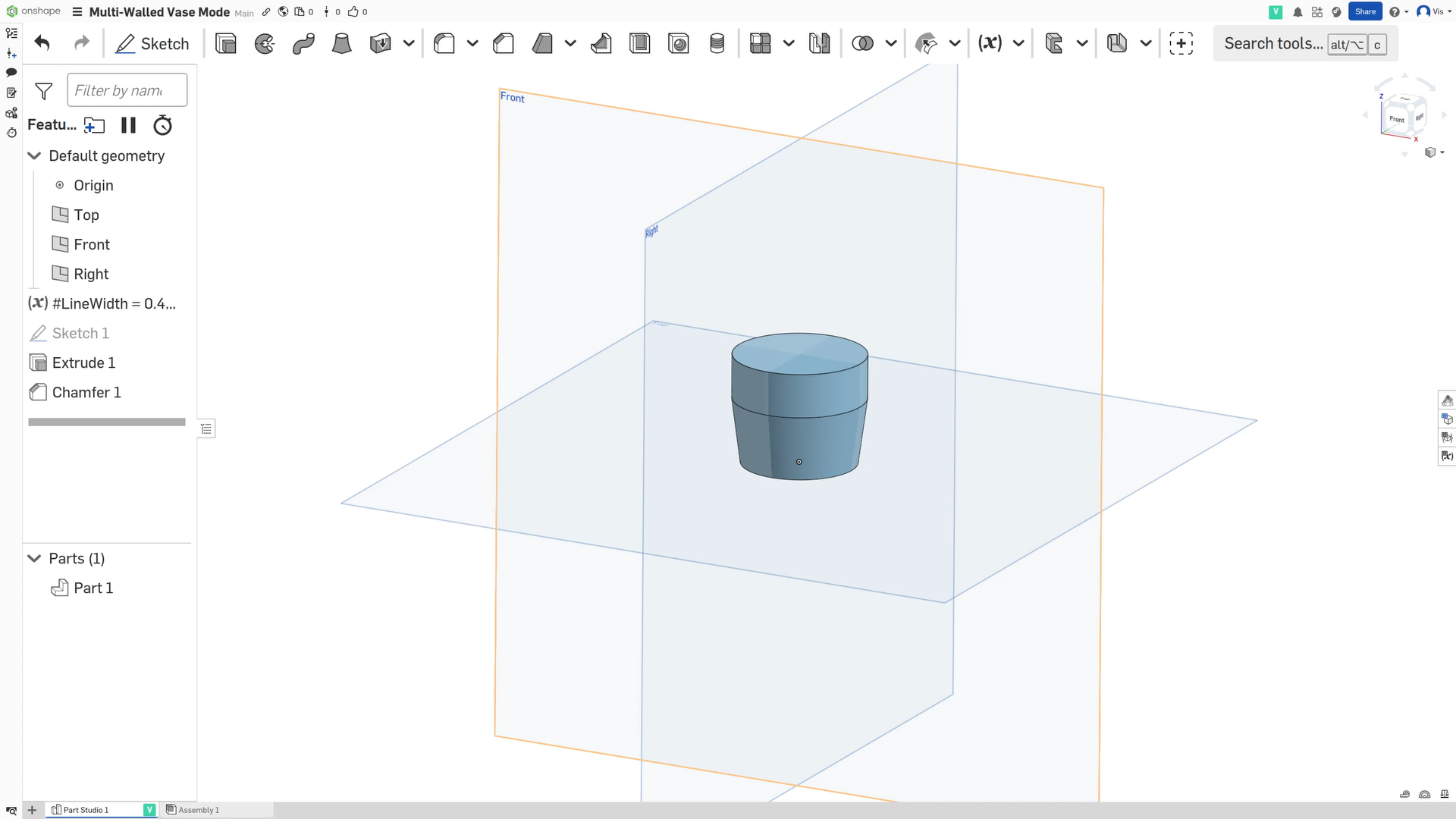
Creating the Base Shape
To get started with this technique, it’s important to focus on designs that would already work well in vase mode. First, we need to define the shape, just like we would if we were designing for vase mode. For this example, I’m going to use a simple pot-shaped container as my base design.
I also recommend setting up a variable for your slicer’s “Line Width”, which will make it much easier to tweak things later on.
Double Walled Vase Mode
Assuming you have your base part defined, and your Line Width variable setup, you can do the following to turn it into a double walled vase mode print. This is the first of the two techniques.
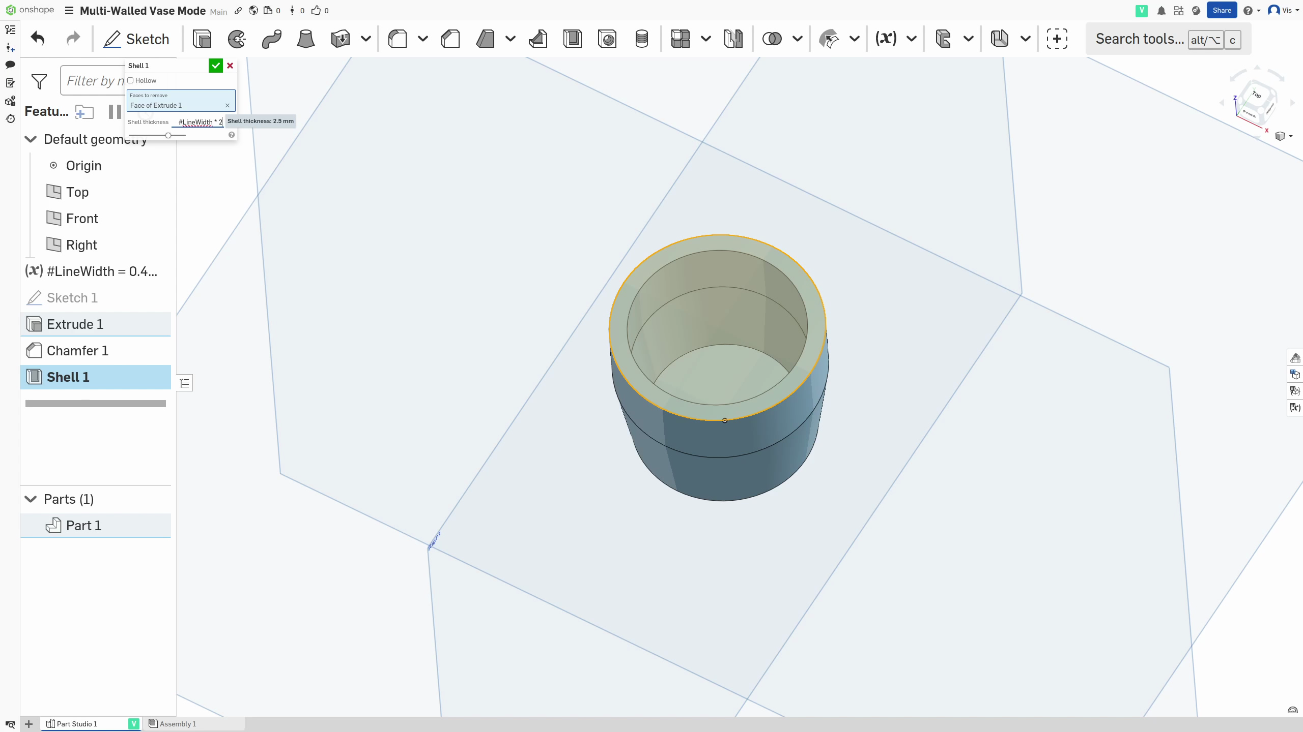
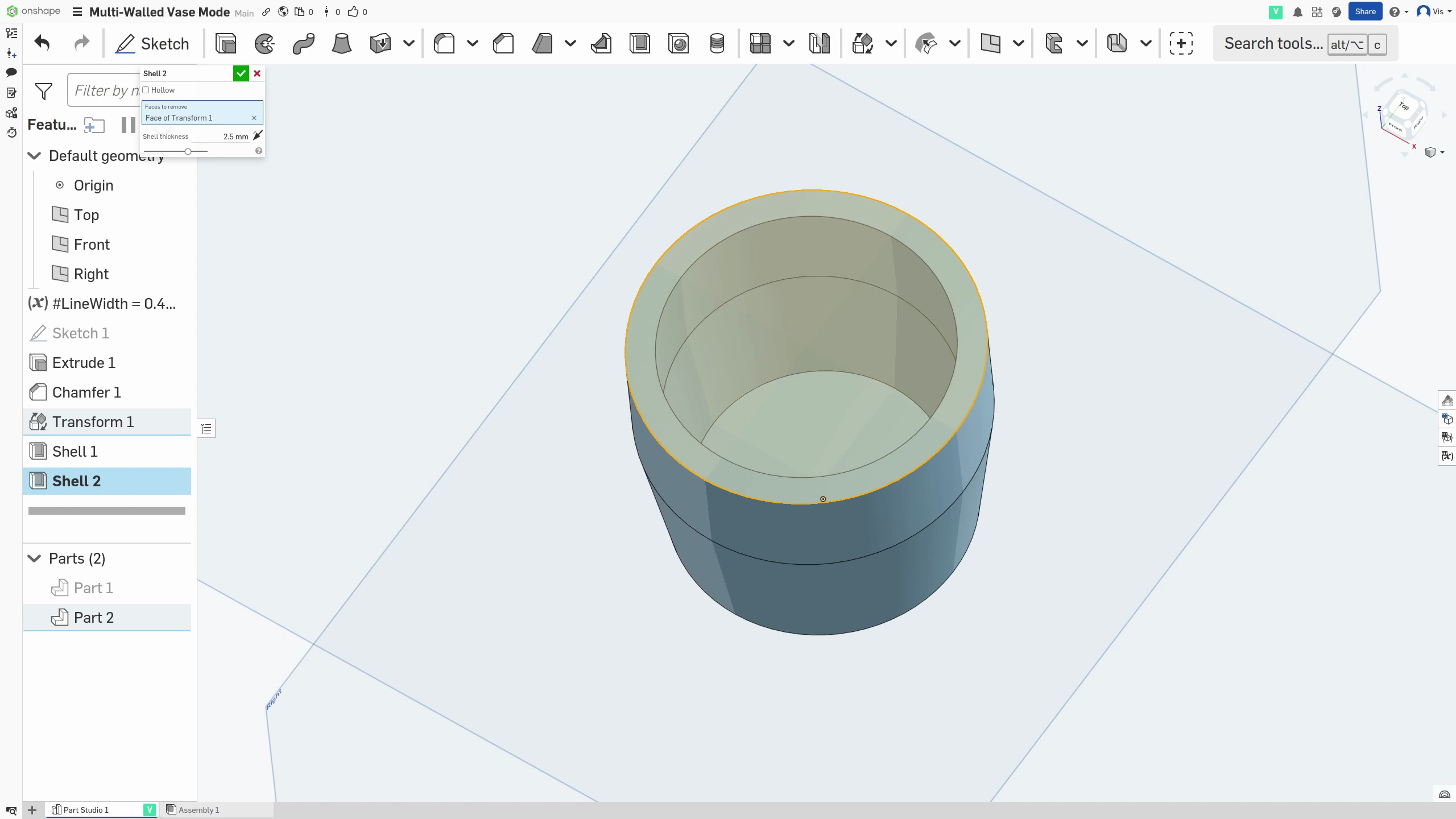
Creating a shell
- Select the
Shelltool (or equivalent) from the toolbar
.png)
- Select the face that Vase Mode would otherwise remove to be shelled. This is most often the top face of the part.
- Set the shell dimension to (Line Width x 2)
- And run the shell operation
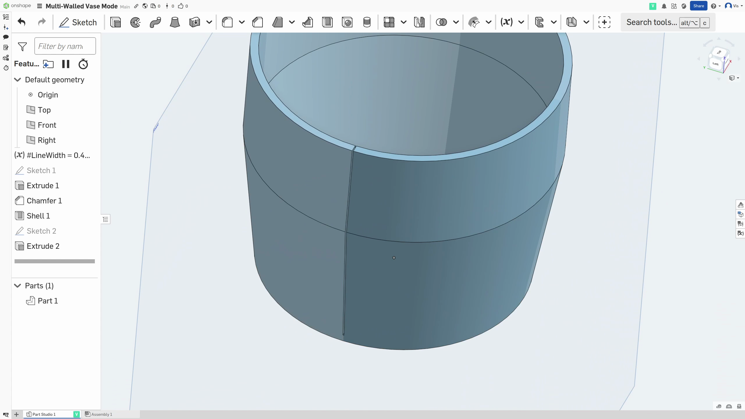
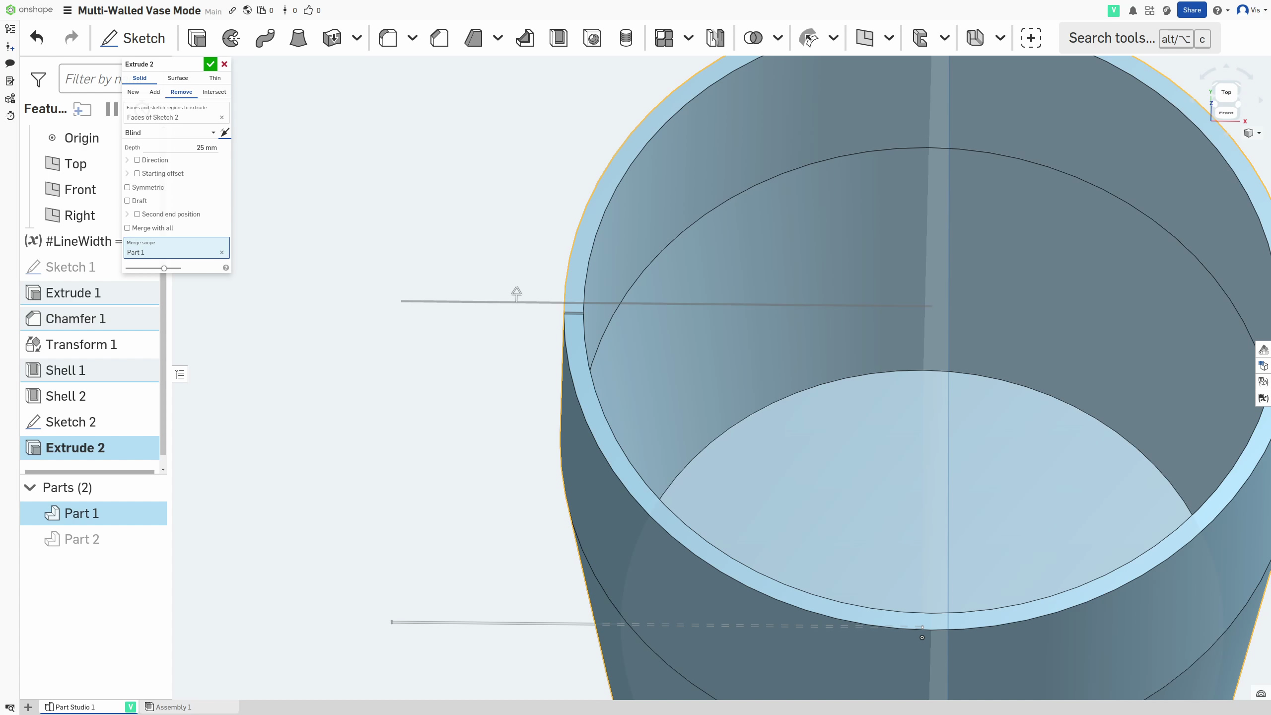
Cutting the slot
- Next, start a sketch on the bottom surface inside the part (I recommend reading the next few steps first as they will context to why you’re doing certain things)
- Draw a rectangle centered with the part along one edge and extending out past the walls of the container. The rectangle should intersect exactly once with the wall of the part
- The dimension of the side of the rectangle parallel or tangent to the side it intersects should be 0.1mm. This will be interpreted as a cut by the slicer but will, in reality, be close enough that the filament creates a strong bond along it
.png)
- Now
Extrudethat rectangle so that there is a clean cut from the base of the part to the top of the wall in just one place in the wall.
This should leave a shelled part with a solid base and a wall with a split of 0.1mm running down it
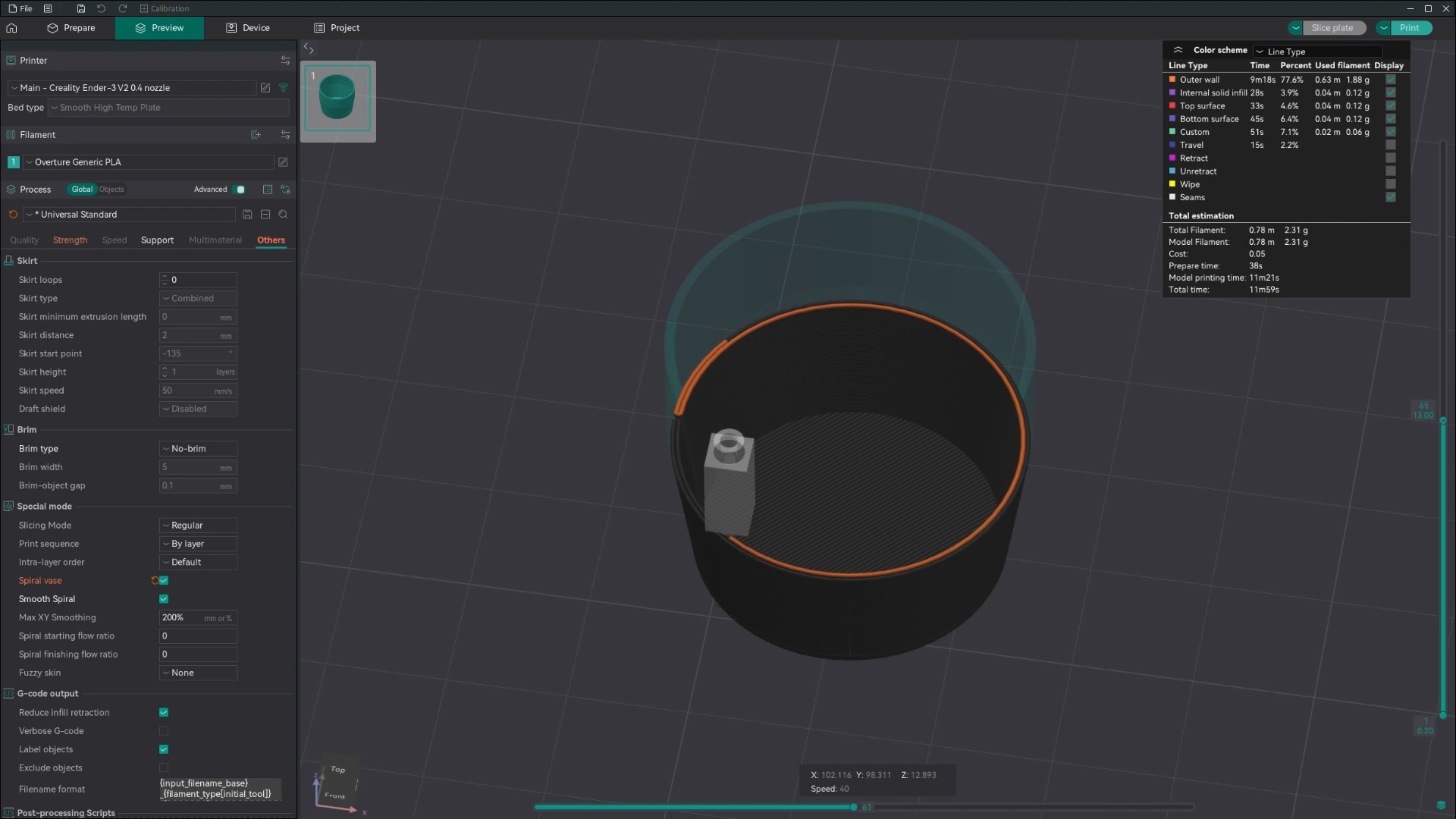
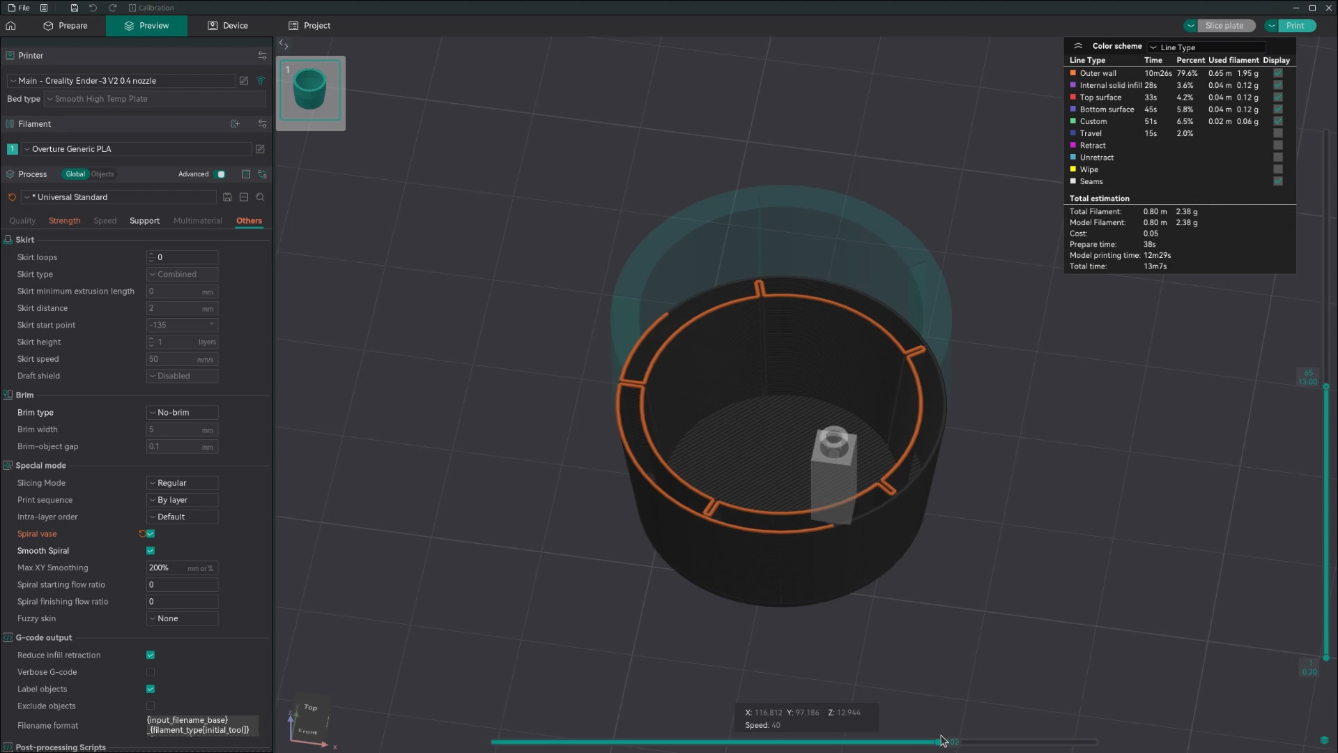
Slicing & printing
Once you’ve exported this part and dropped it into your slicer, just hit vase mode and you should see in the preview that it does two walls for each layer all the way up. The 0.1mm gap will be interpreted as a cut by the slicer but will, in reality, be close enough that the filament creates a strong bond along it.
Ribbed Vase Mode
Assuming you have your base part defined, and your Line Width variable setup, you can do the following to turn it into a ribbed vase mode print. This is the second of the two techniques.
Creating a copy
- First, before anything else, create a copy of the part. This can be done by selecting the
Transformtool, selecting the part and choosingCopy in placefrom the dropdown before accepting.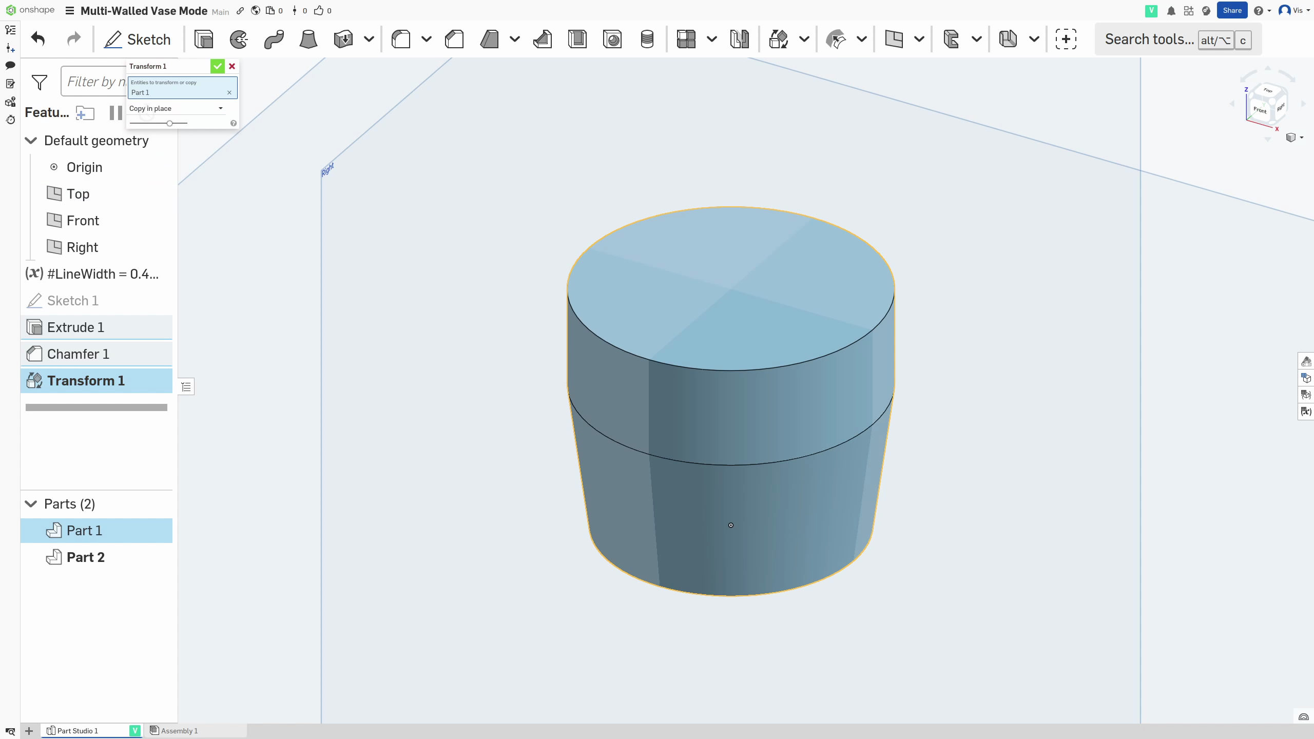
Creating a shell of the original
- Then temporarily hide the copy and work on the original for the next few steps
- Select the
Shelltool (or equivalent) from the toolbar
- Select the face that Vase Mode would otherwise remove to be shelled. This is most often the top face of the part.
- Set the shell dimension to (Line Width x 2)
- And run the shell operation
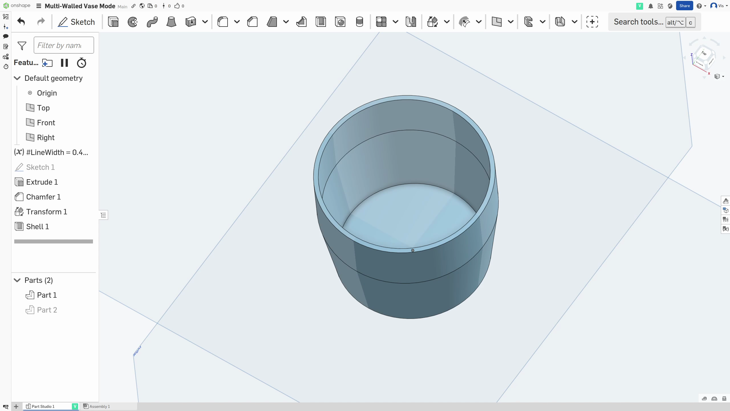
Creating a shell of the copy
- Now temporarily hide the (now shelled) original and work on the copy for the next few steps
- Select the
Shelltool (or equivalent) from the toolbar - Select the face that Vase Mode would otherwise remove to be shelled. This is most often the top face of the part.
- Set the shell dimension to the final wall width, whatever you would like for that to be
- And run the shell operation
Creating a slot in the original
- Now again, temporarily hide the copy and work on the shelled original for the next few steps
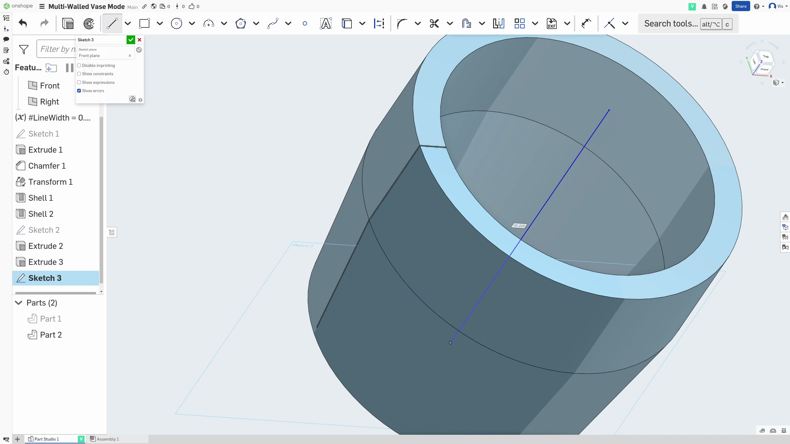
- Next, start a sketch on the bottom surface inside the part (I recommend reading the next few steps first as they will provide context for why you’re doing certain things)
- Draw a rectangle centered with the part along one edge and extending out past the walls of the container. The rectangle should intersect exactly once with the wall of the part
- The dimension of the side of the rectangle parallel or tangent to the side it intersects should be 0.1mm.
- Now
Extrudethat rectangle so that there is a clean cut from the base of the part to the top of the wall in just one place in the wall.
- Just as some quick setup, before continuing, create a sketch on the Front or Side Plane and, on that sketch, draw a straight line from the center of the base going up. The length of this line doesn’t matter, we just need it as an Axis guide.
Creating the slots in the copy
- Once that’s done, once more, hide the shelled and cut original and work on the shelled copy for the next few steps
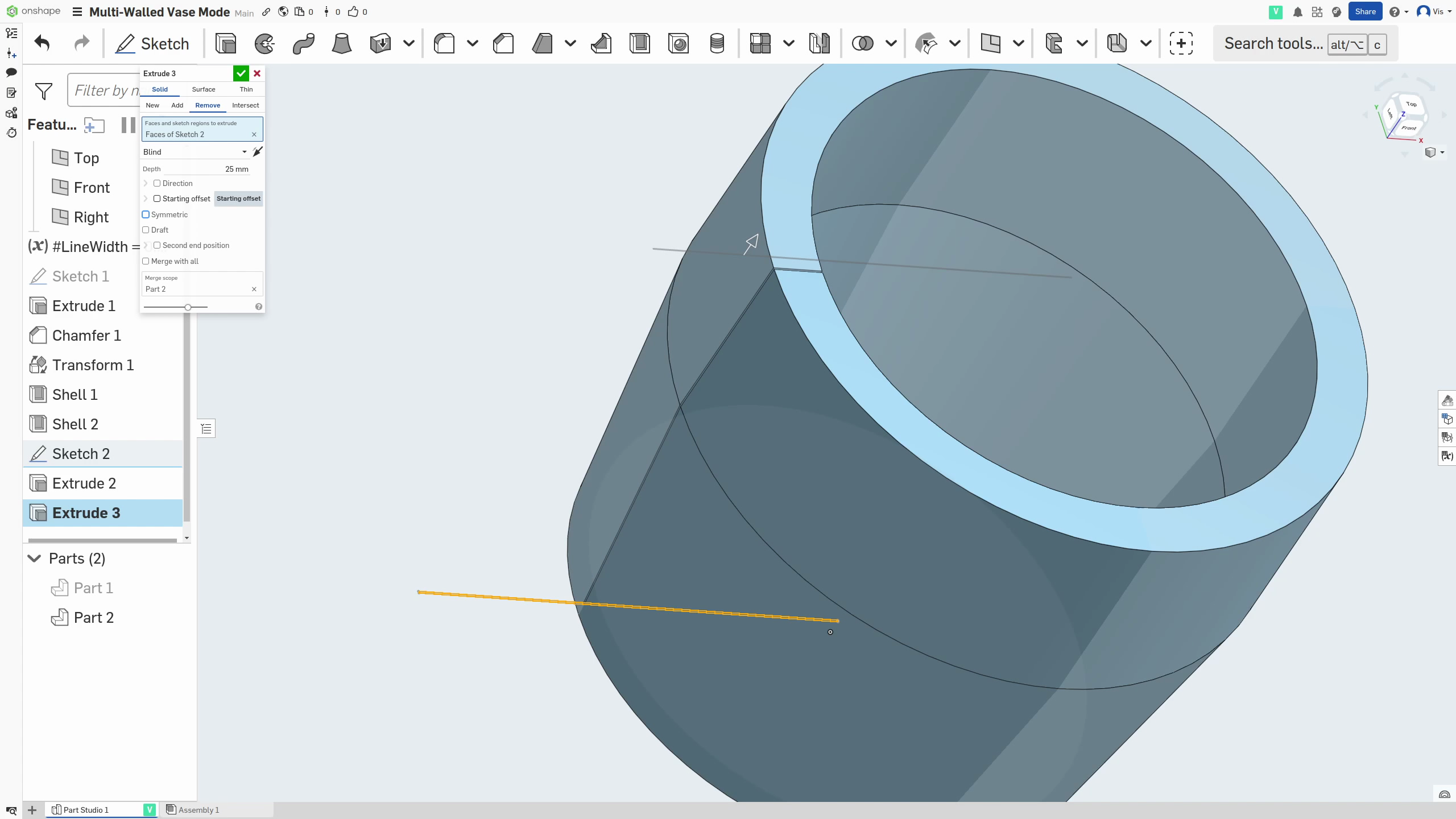
- On the copy, again
Extrudethat rectangle (not the line we just drew) so that there is a clean cut from the base of the part to the top of the wall in just one place in the wall.
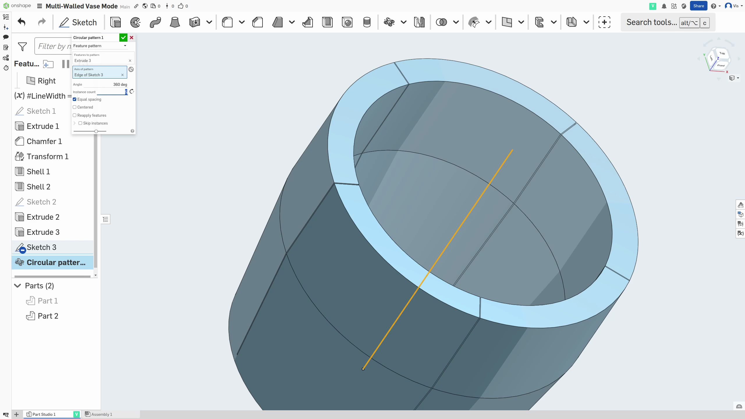
- From there, select the
Circular patterntool
(1).png)
and switch to Feature pattern
.png)
- Now select the cut we just made as the feature and the line we drew as the Axis. You will have to turn on
Reapply featuresif this errors for you initially. 5. Lastly for this, adjust yourInstance countuntil you’re happy with the number of ribs that will be added. Each cut will become a rib.
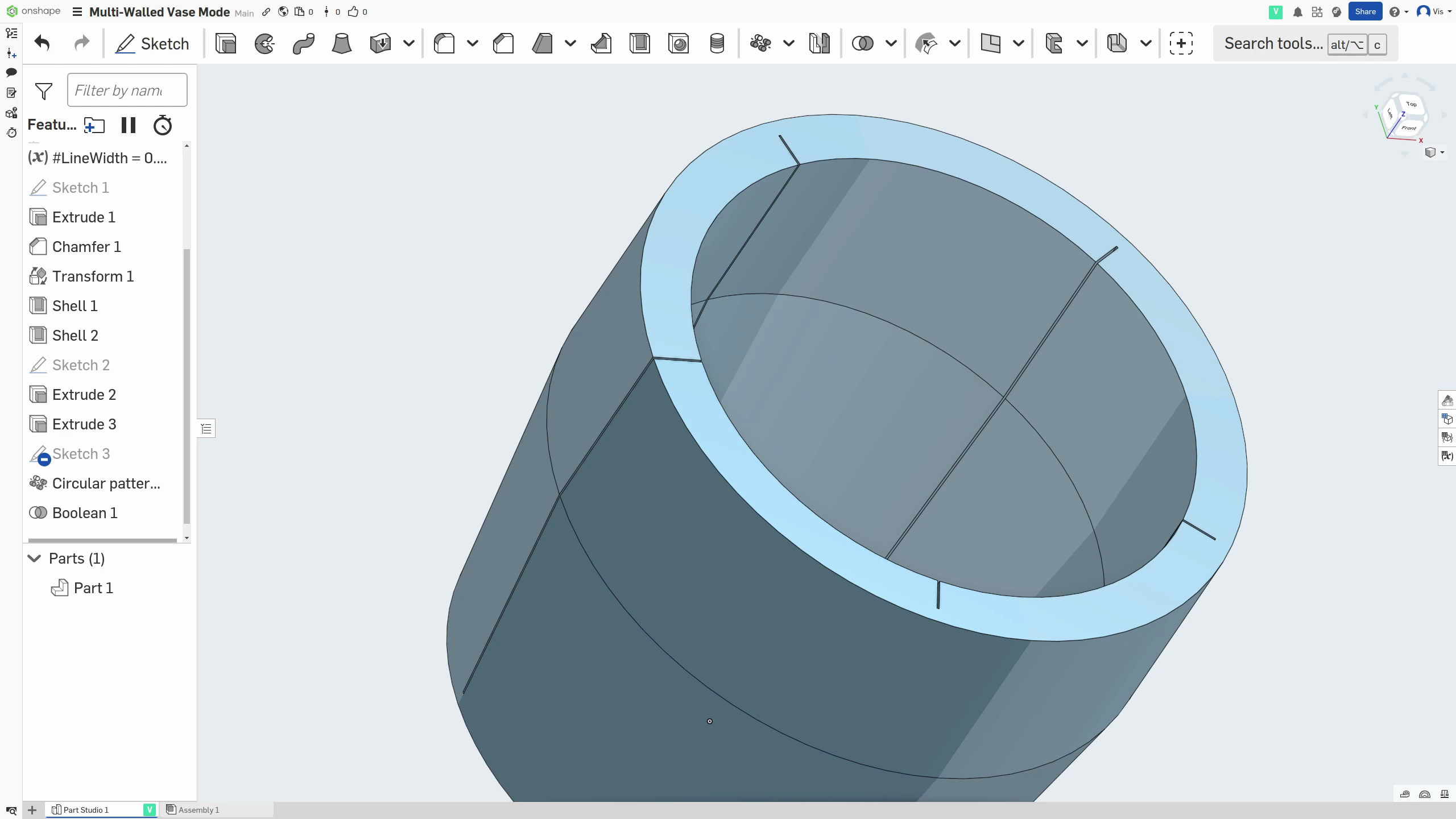
Combining the final part
- This will leave you with a thin shelled part with one cut and a thick shelled part with as many cuts as you selected. The final step is just to Boolean these together!
.png)
This should leave a shelled part with a solid base and a wall with a split of 0.1mm running down it, as well as multiple splits on the inside-only of 0.1mm too.
Slicing & printing
Once you’ve exported this part and dropped it into your slicer, just hit vase mode and you should see in the preview that it does two walls with ribs in one loop, for each layer, all the way up. The 0.1mm gaps will be interpreted as cuts by the slicer but will, in reality, be close enough that the filament creates strong bonds along it.
Conclusion
I hope you found these techniques useful and please do like and share to tell the algorithms you want to see more like this! Also, don’t forget to follow or subscribe for more updates!
You can also join my Patreon for free to access the original download files for the models.
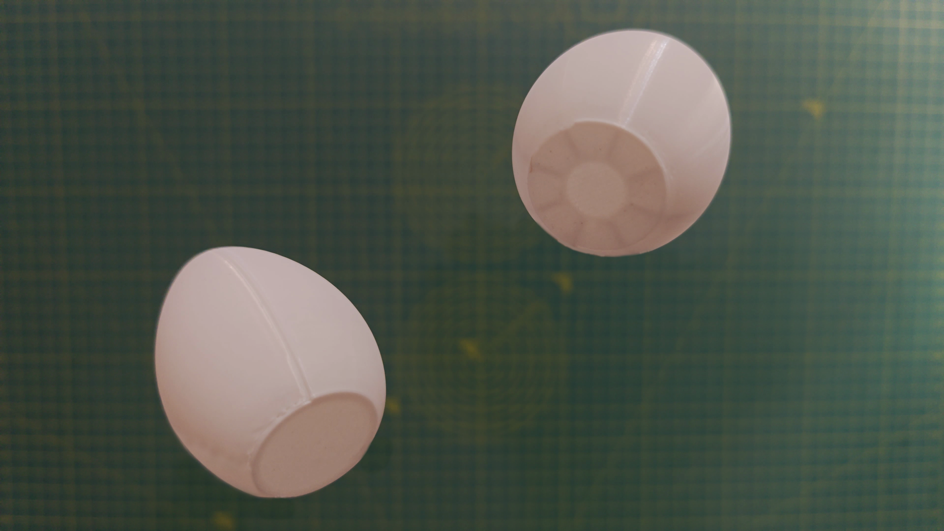
The Patreon post linked includes some models I made by remixing amazing existing designs. Feel free to print them out and test their strength! I especially recommend the egg!
.png)
.png)